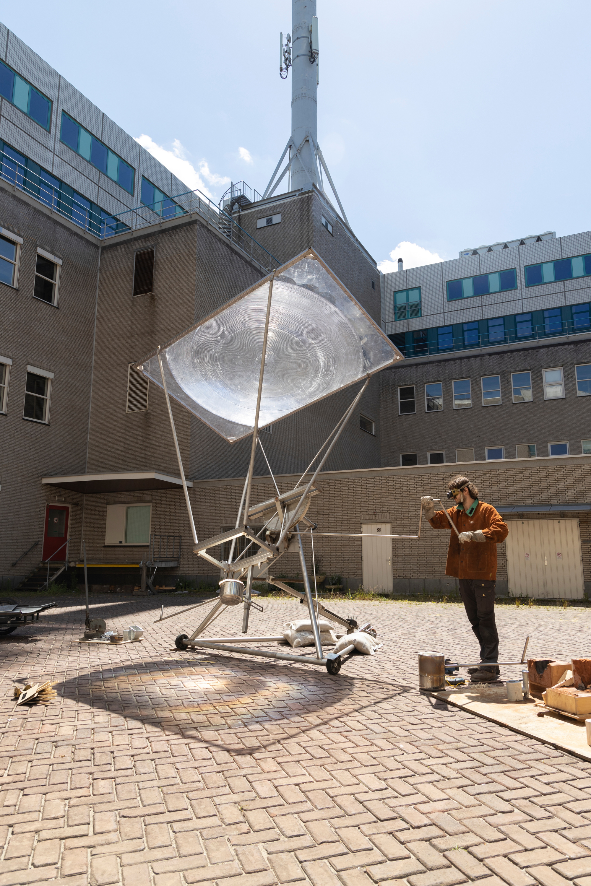
Solar 3D Printer: my take on Markus Kayser's Solar Sinter
Following up on this hastily edited post about using the Sun to extract some form of hydrogen and to decarbonate part of the construction industry, I present this Solar Desert Sand Vitrifier I have been working on.
 Link to simulation code and to the simulator: MuJoCo.
Briefly
My goal is for this machine to be able to print house walls by melting desert sand with focused sunlight. Requiring only highly available and renewable energy and material.
Building on Markus Kayser’s Solar Sinter I designed and sized a prototype which should…
- use a Fresnel lens
≥1.5m2area (Markus Kayser’s lens that we know can melt desert sand) - translate and rotate the lens within a print volume
100xlarger than Solar Sinter’s 40cmx40cmx40cm - achieve mean print speed
≥1cm/minwhich seems slower than Kayser’s machine (from the video) - calibrate extra easily, with positioning
tolerances in cm - cost
≤1000€. Much cheaper than$28kQT10-15,$39kBigRep-ONE or>$1.5MVX4000 as well as orders of magnitude worse precision and speed.
Lens
Finding a large circular Fresnel lens was tough!
First I looked for cheap Fresnel lenses from (broken) 80s-90s-00s Rear-projection TVs on my local equivalent to Craig’s List. The few I could find ended up not large enough.
Here’s the result of around a minute of summer sunlight exposition around midday at Paris latitude with a AA67-00115B (Samsung SP43T8HPX/BOB) 43” (=0.63m2) lens: 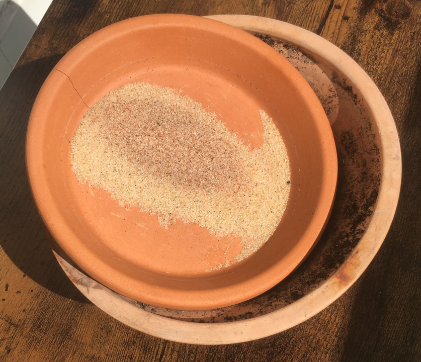
Then I went for the modern 65” (=1.2m2) flatscreen TVs but these turned out to only sport linear Fresnel lenses! Meaning they focus light into a line and not a single spot. Also, you wouldn’t believe how much money some people ask for a once expensive but utterly smashed screen…
On AliExpress I could only find lenses in the meter square area. To melt sand we must achieve temperatures ranging from 1000 to 1500 degrees Celsius and talking with different sellers (as well as a French one selling the cheapest lenses I found) all were confident temperatures upwards of 800-900C weren’t achievable…
In the future I’d like to come back to these cheap-ish Chinese lenses ($200-$700) and get a deal as there are a lot of competition there. Also, see these exhorbitant shipping fees lately ($600 for a 1.2m2 lens priced $250)? But first I need to replicate results!
I ended up finding CF1200-B2, a 1.5m2 PMMA rectangular spot lens with a smallish focal distance of 1.2m. Note that acrylic (PMMA) is as good as glass for lenses and is usually lighter (3.5kg here). This turned out pretty expensive: 250EUR/piece, 500EUR shipping to EU, 120EUR customs.
Again, bulk pricing is required here if I ever want to achieve less-than-a-thousand euros per machine…
Imaging lens
Let’s engineer a brick-printing lens: a Fresnel lens that produces a rectangular image so that the lens needn’t be moved on x-y (it only needs to be normal to the Sun).
- Blender: simulate parametric fresnel lens to produce a specific image (instead of point-focus or linear)
- github.com/rafael-fuente/diffractsim
ultra thin lenses
- https://youtu.be/CT_9EyOCivU?t=23
- https://www.solarbrother.com/en/buy/fresnel-lens-xl/
- https://heliac.dk/
- Unfortunately, we will not be able to support you as we have decided to no longer sell lenses but only focus on our large-scale, integrated solar fields for industries and district heating.
- For the same reason we will not be able to develop a custom lens mold.
- Heliac’s 2018 Solar Cooker
-
Focal length (cm) Spot size (cm) Length (cm) Width (cm) Weight (g) Cost (€) 200 8 140 109 300 10 73 1 82 48 70 5
-
..WIP..
Large print volume
co2 emitted per kg of plastic vs aluminumlifetime of plastic vs aluminumstrength of 3d printed screwshollow screws are possible
-
ask asca films for enough samples to cover outside cube frame with such that there is enough power outputed to not require non-organic ones -
make parts of the corner pieces removeable so some can be replaced and even upgraded or help grow larger scale iteration in the end the printer may look like a plastic kleenexuse thermoplasticity to create a Fresnles lens + stand that follows the Sun (Tournesol) faster than the print head has to move
-
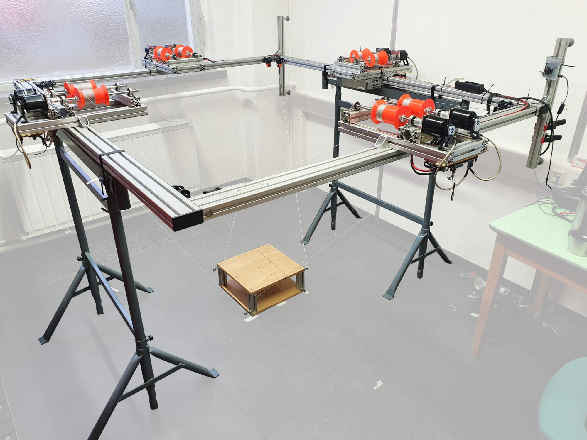
the more shippable the printer the better chance it has of selling kits open cable robot project
motors
- https://makersportal.com/blog/raspberry-pi-stepper-motor-control-with-nema-17
- Raspberry Pi pins
- Python
-
=> enough pins in just one RPi? - https://www.omc-stepperonline.com/sale.html/clearance-sale-nema-17-stepper-motor-bipolar-l-48mm-w-gear-ratio-27-1-planetary-gearbox.html
- https://www.omc-stepperonline.com/download/17HS19-1684S-PG27.pdf
- 17HS19-1684S-PG27
- Motor Type: Bipolar Stepper
- Holding Torque without Gearbox: 52Ncm(73.6oz.in)
- Planetary Gear Ratio: 26.85: 1
- $24
- =>
52*26.85/100 N.m- =>
~1.4kgmax hold per motor
- =>

- A BLK A+ 1B
- C GRN A- 1A
- B RED B+ 2B
- D BLU B- 2A
- 2b 2a 1a 1b
-
red blu grn blk
- https://www.amazon.fr/drv8825-Module-dissipateur-thermique-exemple-Imprimante/dp/B01JIW13RY
- DRV8825 / A4988 motor driver
- ~ 4EUR per motor
- https://www.amazon.fr/Jeanoko-Control-Shield-DRV8825-imprimante/dp/B08VVZZB81
- support for DRV8825 / A4988
- ~ 6EUR per motor
- https://www.amazon.fr/CQRobot-Pieces-JST-PH-Connector-Female/dp/B0731MZCGF
- JST 2mm 4p connector
- stepper motor -to-> DRV8825 support card
- JST 2mm 4p connector
- https://www.adafruit.com/product/2348
- RPi HAT
- USD23 / each adds 2 steppers
- https://learn.adafruit.com/adafruit-dc-and-stepper-motor-hat-for-raspberry-pi
- 1.2-3A
- 4.5-13.5VDC
- stacking header
spring+cable system x4 to hold lens down
- 3d print circular spring
- Auto-Rewind Spool Holder mechanism
- spiral spring
- vacuum cleaner power cable mechanism
- 3d print cord rewind
- MARBLE THROWER 3D print model
- EUR10 Vicloon Porte-clés Yoyo,Enrouleur Rétractable Longueur 70 cm avec Ressort Renforcé et Cordon Résistant,pour des Cartes d’identité avec Porte-clés Clip de Ceinture et le Crochet de Serrage
- Enrouleur Rétractable
- EUR10 Enrouleur retractable avec clip ceinture et crochet. Réenroule jusqu’à 180g
- EUR37 Longe porte-outils anti-chute ceinture rétractable à enrouleur automatique ERGODYNE 3010 122cm 2.2kg
- EUR10 Deolven Porte-Clés à Ressorts à Spirale,7 Pack Extensible Porte-clés en Plastique Coloré Cordons de Pêche Rétractable Sangle en Spirale d’attache pour Clés Torch Pinces École 7 Couleurs
- EUR9 Porte-clés rétractable robuste Kuuqa - Enrouleur avec 100 cm de fil d’acier, noir
- EUR11 Ferplast Flippy Small Deluxe Laisse à enrouleur pour petits et moyen chiens Violet
- EUR65 Enrouleur mural encastrable avec sangle rétractable Fix
- 1kg 1.2m RETRACTABLE TOOL LANYARD REFERENCE : TS9000108
- EUR290 Barrière de sécurité à enrouleur rétractable - Barrière à sangle robuste avec crochet (15-25 m)
- EUR9 Fil Linge Retractable, Corde À Linge Rétractable, Bobine De 12 M, Enrouleur De Corde À Linge Extensible, Économise De L’espace (gris Argenté)
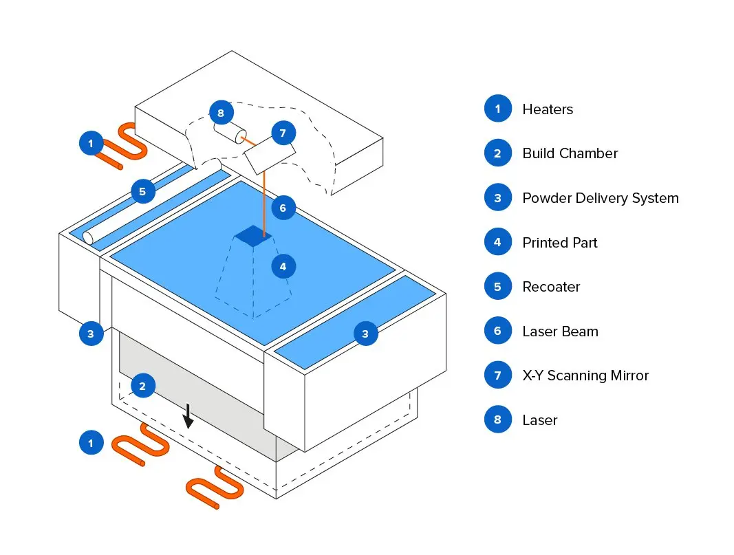
Change powder delivery system
Improve on Markus Kayser’s Solar Sinter by replacing ③ & ⑤ with a powder deposition system inspired from FDM: Fused Deposition Modeling.
vibrating tube
- inject powder through a tube
Cubic frame material
Curtain pole (interior diameters) (Castorama)
- 28mm 2.5m wood(ash) 11€/m
- 16mm 2.5m metal(brass) 5€/m
-
19mm 2.5m metal(white black) 7€/m - 19mm 2.5m metal(brass) 8€/m
- 28mm 2.5m metal(brass) 13€/m
- 28mm 2.5mm metal(nickel) 12€/m
- See also: elbow connector 10-13€/p, bracket 11-15€/p.

European Standard Rail Aluminum Extrusion Profile
Photocatalytic water splitting
- (2010), Efficient Solar Hydrogen Production by Photocatalytic Water Splitting: From Fundamental Study to Pilot Demonstration
- The object of our work is to explore the possibility of mass solar hydrogen production by coupling photocatalytic reactors with solar light concentrators
- a hydrogen production rate of 0.164 L/h per unit volume
- this technology to be economic[ally] viable in the near future
- it is necessary to narrow the band gap of photocatalysts to harvest visible-light*
- (2013), Metal sulphide semiconductors for photocatalytic hydrogen production
- sulphide semiconductor photocatalysts have excellent solar spectrum responses and high photocatalytic activities
- we highlight the crucial issues in the development of highly efficient sulphide photocatalysts without noble metal cocatalysts
- These studies show not only the possibility of utilizing low cost carbon materials as a substitute for noble metals (such as Pt) in the photocatalytic H2-production but also a significant enhancement in the H2-production activity using metal-free carbon materials as effective co-catalysts.
- (2020), Ultrafine nano 1T-MoS2 monolayers with NiOx as dual co-catalysts over TiO2 photoharvester for efficient photocatalytic hydrogen evolution
- (2020), Recent progress on ammonia fuel cells and their potential applications
- ammonia fuel cells offer a clean and reliable energy source, which can mitigate many of the limitations associated with hydrogen economy and contribute to a more nearby sustainable future
- (2021) Photocatalytic solar hydrogen production from water on a 100-m2 scale
- we here report safe operation of a 100-m2 array of panel reactors over several months with autonomous recovery of hydrogen from the moist gas product mixture using a commercial polyimide membrane
- While the hydrogen production is inefficient and energy negative overall, our findings demonstrate that safe, large-scale photocatalytic water splitting, and gas collection and separation are possible.
- Is PLA heat resistant? ABS, ASA, PETG and more
- PC: Polycarbonate (resists 150°C) but is on the expensive side & often blended for those of us without an industrial-grade 3d printer
- ABS (resists 105°C) cheap, tough but careful with the toxic fumes
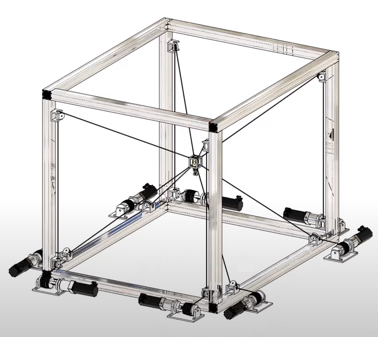
- (2021) Motor Current Based Force Control of Simple Cable-Driven Parallel Robots
- https://ropebot.eu
- Jonas & Konrad from ropebot.eu
-
Motors
Cameras
- https://webcamtests.com/
- 15EUR TAKRINK Webcam 1080P Webcaméra Cybercaméra Ordinateur Microphone Intégré Port USB avec Couvercle de Webcam Trépied pour Chat Vidéo et Enregistrement
- 30EUR grand angle=>all feets in picture Webcam PC 1080p HD - eMeet Nova Webcam Streaming Mise au Point Automatique avec Double Microphone, Web caméra USB pour Ordinateur Portable, Grand Angle 96°, Plug & Play, pour Linux, Win10, Mac
- “Run openpilot with webcam on PC”
- at least 720p and 78 degrees FOV (e.g. Logitech C920/C615)
- https://openmv.io/collections/cams/products/openmv-cam-h7-plus
Vision things
reflective film- EUR10 Salzmann 3M Diamond Grade Autocollants réfléchissants imperméables Équipée de 3M Scotchlite Autocollants pour les voitures, les motos, les bicyclettes - 4pcs
- EUR9 24 Pcs Autocollants Réfléchissants d’Avertissement Stickers Réfléchissants de Sécurité Stickers de Visibilité Nocturne Autocollants de Bande Imperméables pour Véhicule, 1,18 x 3,25 Pouces
- EUR5 Wowow 3M Bande réfléchissante - Ruban adhésif - Reflective tape - Blanc
- EUR12 10M Ruban D’avertissement Réfléchissant, ONTWIE Sécurité Réfléchissant Avertissement éclairage Autocollant Ruban Adhésif Rouleau Bande, Couleurs Blanches pour Beautify Vélo Moto Décoration - 2.5cm
- EUR15 ONTWIE Ruban Réfléchissant étanche Haute Visibilité Marquage Industriel Danger Heavy Duty Attention Attention Ruban Auto-adhésif de Sécurité Extérieur - Rouge 10M
- 4 Point OpenCV getPerspective Transform Example
Fibers
- Dyneema braided x12, 0.18mm diameter, 16.22kg, 130m for 30EUR
=> 0,24€/m- Should hold my <5kg loads. Maybe I should’ve gone for a thicker string?
- Anyway that is 5x cheaper than the 1EUR/meter string that was mentioned.
- VGEBY Pêche Split Rings, 200 Pcs 5Tailles Heavy Duty Acier Inoxydable Split Anneaux Solide Connecteurs De Pêche Attirail De Pêche
- Dovesun Fishing Rod Repair Kit Fishing Rod Guide Repair Kit Rod Ceramic Guides Ring 12 Sizes 0.15in to 1.18in
- Tobben from Hangprinter
- used in v4 = ceramic ring from sewing machines
- EUR14 MaoXinTek Guides pour Canne à Pêche, 80 pièces Kit de Réparation Anneau Guide de Pêche Céramique en Acier Inoxydable et Carbone pour Canne à pêche télescopique
- Company Makes Bikes With Strings Instead Of Chains
- EUR9 300m Dyneema Spectra Extreame Braided Fishing Line Super Strong Multifilament 4 Stands Fishing Wire
-
EUR45 Kanirope® Corde dyneema PRO 1mm 100m noir 12x tressée SK78 pré-étirée enrobée
- https://hackaday.com/2017/10/12/this-3d-cable-printer-remixes-the-delta/
cable robot camera standfuture: CDPRstackablecan climb up/downcan extend framecable holders can move/rotate/slide on the inner frame so multiple CDPRs can work in a tight volume simultaneously
Name?
- not:
Shai-Huludhttps://dune.fandom.com/wiki/Shai-Hulud - not: the
drej - le peuple des dunes en breton:
erinhttps://geriafurch.bzh/fr/brfr/erin- dune de sable / dune sablonneuse :
erin - sable fin :
traezh munut - sable / sable maritime / sable de mer :
traezh - dune :
tevenn
- dune de sable / dune sablonneuse :
Voir le monde dans un grain de sable~ William Blake
Crucibles
- EUR16 Foundry Clay Graphite Crucibles Black Cup Furnace Torch Melting Casting Refining Gold Silver Copper Brass Aluminum
- EUR11 Moule De Fonderie De Fonte De Coulée De Graphite De Grande Pureté De Werse Pour L’Or Et L’Argent - 750G
- EUR18 Pomcat Gants résistants à la chaleur d’un fourneau pour le raffinage des métaux précieux 33 cm

- https://www.thingiverse.com/thing:2932583
thread spool guidethread groove- https://www.thingiverse.com/thing:3184816
wear_groove_NB.stl
jointstetra angle joinery- https://www.thingiverse.com/thing:996842
- https://github.com/SolidCode/SolidPython
- https://github.com/openscad/openscad
held tightly to the motor shaft with a set screw in an inserted nut- https://www.goilacog.com/index.php?main_page=product_info&products_id=148603
lead screw- https://www.thingiverse.com/thing:40642/files
AJGW-GearsHering_Small.stl
- Low cost metal 3D printing! Electrochemical additive manufacturing

model sun>8 ropes & lens>light cones>ellipsys on sandbedbonus points when normal to Sun
learn ellipsys->motor speeds (+/-/0)state0-to->stateNvia speed chunksmay assume only one (2) speed setting(s)
genetic?
So for my solar printer project I need to come up with the reverse kinematics so as to trace a light path on the sand surface
Meaning: I have to trace this path on the ground with sunlight, how do I move each of the 8 cables to achieve this path?
I'd like to learn that task instead of coming up with the maths. I have a camera looking at the ground + 3-4 reference points to correct the trapeze of the camera (since the webcam is a bit above the ground)
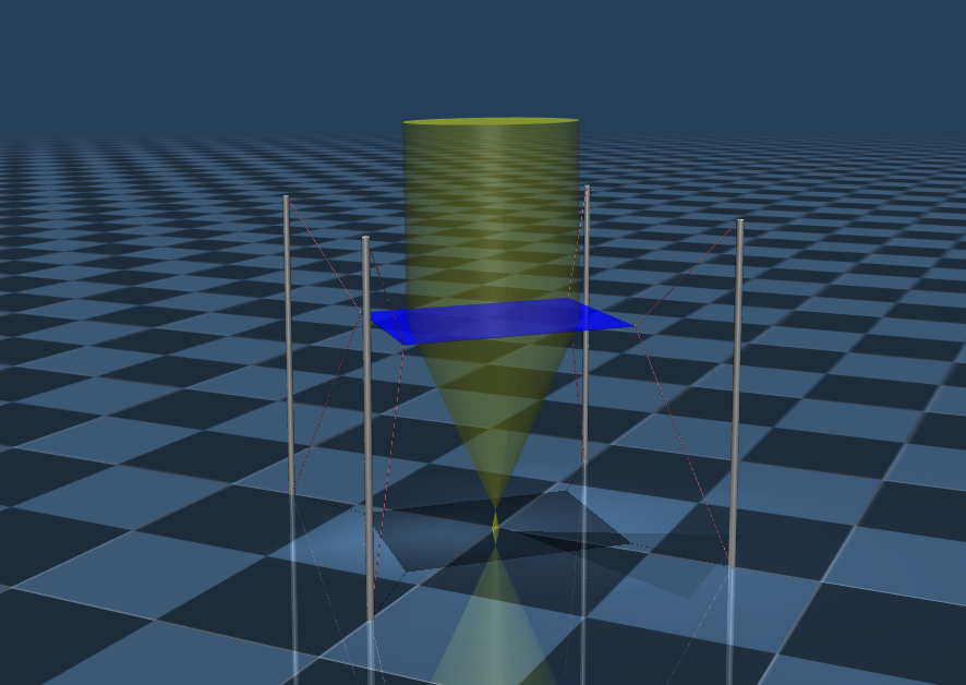
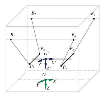
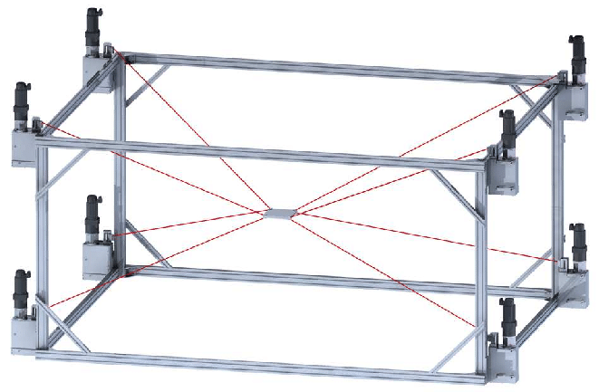
I found https://deepmind.com/blog/announcements/mujoco which I believe can help with data generation. I plan to simulate 8 rigid cables, one at each corner of a cube. Each cable is attached to a square plane in the middle of the cube (2 cables per corner of the plane, one coming for above one from below). Then I have two cones coming out of that square (ie. my lens). The cones connect at the lens' focal length. Then, from moving each cable I can look at the intersection of these cones with the ground (an ellipsis).
Now my learning task is to control how to move the cables so that the intersection is close to being a dot. Others have solved the maths before so I guess this should be learnable...
My question then: what kind of AI model should I be training on this synthetic data (8 motor input speeds [-1;1] + ellipsis shape and position relative to the center of the ground) ? An LSTM?
cdpr inverse kinematics
- Jean-Pierre Merlet
- (2021) Mixing neural networks and the Newton method for the kinematics of simple cable-driven parallel robots with sagging cables
- (2015) Kinematics and statics of cable-driven parallel robot by interval-analysis-based methods
- (2021) Efficient Kinematics of a 2-1 and 3-1 CDPR with Non-elastic Sagging Cables
- (2020) The Prince’s tears, a large cable-driven parallel robot for an artistic exhibition
- (2004) Multi-criteria optimal design of parallel manipulators based on interval analysis
-
(2004) Interval method for calibration of parallel robots: Vision-based experiments
-
https://docs.lyceum.ml/dev/lyceumai/algorithms/naturalpolicygradient/
- (2019) Control of a Cable-Driven Parallel Robot via Deep Reinforcement Learning
- rlcoach
- https://www.gshi.me/blog/NeuralControl/
- https://github.com/bencbartlett/3D-printed-mirror-array
crazy art with CDPRs
Caption this pic.twitter.com/5E0HmXfLWy
— Amazing Physics (@amazing_physics) January 2, 2022
large-scale seawater desalination plant
- https://github.com/aidanscannell/pilco-tensorflow
- https://github.com/deepmind/dm_control/blob/master/dm_control/mjcf/README.md
- https://github.com/openai/mujoco-py/blob/master/examples/markers_demo.py
- https://github.com/deepmind/acme
helical piling
-
https://www.designboom.com/architecture/magnus-larsson-sculpts-the-saharan-desert-with-bacteria/
- https://urbanutopias.net/2019/09/01/arcosanti/
- https://en.wikipedia.org/wiki/Arcosanti
- https://www.archdaily.com/517456/inside-masdar-city
dunes divert wind patterns
- https://en.wikipedia.org/wiki/Sand_dune_stabilization
- (2014) Echo Dune
- An echo dune is a topographically anchored (static) high-order bedform with a single crescentic slip face parallel to a topographic obstruction (e.g., cliff, rock) ≥60° in slope.
- artificial ocean dune
- compound dunes
- mega-dunes, or draa
- https://www.britannica.com/science/barchan
- https://en.wikipedia.org/wiki/Iva_(plant)
- https://en.wikipedia.org/wiki/Spartina_patens
- https://en.wikipedia.org/wiki/Hudsonia
- https://en.wikipedia.org/wiki/Spartina
- https://en.wikipedia.org/wiki/Cakile_maritima
- https://en.wikipedia.org/wiki/Honckenya
- https://en.wikipedia.org/wiki/Ammophila_arenaria
- (2008) Chapter Three: Topography of the Great Sand Sea
- (2013) Suitability of Recycled Glass Cullet as Artificial Dune Fill along Coastal Environments
lens support structure
- Profilé de carrelage intérieur Diall rond PVC noir lisse 23mmx250cm
- GAH PROFILÉ D’ARRÊT À CARRELAGE
- Profilé de finition aluminium L.2,50m H.6mm
- Profilés de finition chrome pour panneau mural - 2 profilés de 10x5x2100 mm – FINISH MURAL CHROME
building strong is the backbone of society
- frame
Truffaut support bâton 180cm 16mm 12x3.99€70EUR Tonnelle pliante 3 x 3 M - Tecto Bleu - tente de jardin Pop UP, Pergola pliable, Barnum- parasol deporte
- pieu vissé
- Manivelle anti-retour
- Anti-reverse crank
regolight
emergency shutdown
lens top protection
Another, bulkier one here
numbers
- Heat production of magnifying glass
- solarbrother’s lens:
f=200cm=> image radius is200cm*10e-3 = 2cm=> 4cm2 (ideal) spot size (spec says 8cm)- =>
(1.05*1.41)/((2 * 10e-3)**2) * 1000=3.7MW/m2??
- NTKJ’s 120cm focal lens:
- =>
1.44cm2spot size
- =>
- solarbrother’s lens:
- Calculation of Solar Insolation
moving frame
Making our own Fresnel lenses
- it’s not easy…
- How to Make a Lens Through Silicone Molding
- Make Your Own Optical Lenses
- …but at scale?
- Jelle Seegers’s Solar Metal Smelter
the lens is a fresnel lens machined with a hand made jig from polycarbonate, and afterwards polished with methylene chloride.
pulleys
powering steppers off
- stepper enable toggle fast
- https://forum.arduino.cc/t/stepper-control-with-multiple-momentary-toggles/555587/4
- stepper complete shutdown
- https://marlinfw.org/docs/gcode/M018.html
- stepper disable shutdown
- https://forum.arduino.cc/t/turning-off-a-stepper-motor-with-code-not-hardware/354506
rpi4 auto-join wifi list
heat reflector + windscreen
- ASR Outdoor 10 Panel Wind Shield Heat Reflector Compact Collapsible Aluminum Panels
- https://www.screwfix.com/p/radiator-reflector-foil-470mm-x-4m-1-88m/88629
- https://www.wildernessshop.com.au/products/msr-heat-reflector-windscreen-all-models
- reflecteur mirolege
xy cable system
- synchromesh drive system
- Positron V3.2 BOM V5
- Synchromesh Drive Systems
- Very Large Cable Driven CoreXY Mechanism
- fresnel lens on a roll + engineer lens so projected image is a slice of silhouette + only moving part is lens rolling and sand layer deposition